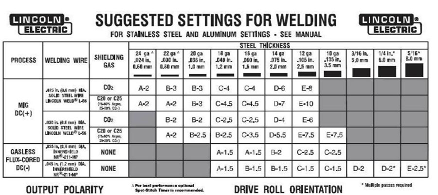
MIG Welder Settings for Various Metal Thickness’s
MIG Welder Settings can vary substantially from model to model and certainly from brand to brand. This article is more a general guideline to help the novice welder understand how the various settings will affect your results. Unlike welding with a stick welder, MIG welding is a semi-automatic process. The welding itself requires very little skill providing the MIG welder settings are correct for the application. The information in this article pertain to welding with solid wire. When welding with Flux Core wire, the parameters can be entirely different.
Factors that Affect MIG Welder Settings
You will need to make adjustments to the MIG welder settings based on a variety of criteria. Before you start welding make sure you understand how these setting affect the welding process. You must consider the following factors:
- The type of metal you will be welding
- The type of gas needed
- The thickness of the metal
- The Cleanliness of the joint
What Type of Metal are You Welding?
The type of metal that you will be welding has a great influence on MIG Welder settings. The material also determines the wire size and material as well as the gas needed. The metals that can be welded with a MIG machine can be grouped into three basic classifications:
- Carbon Steel, also referred to as mild steel or A36
- Non-Ferrous Metals, Aluminum, Copper & Titanium
- Stainless Steel and other Nickel Based Alloys
What Type of Gas do you Need?
Sheilding gas is used in the MIG Welding process to prevent exposure of the molten puddle to oxygen, nitrogen, and hydrogen that are present in the atmosphere and will contaminate the weld. For optimum results you need to use the proper gas for the type of metal being welded. The flow rate of the shielding gas will also play a factor. Refer to the manual that comes with your machine to find the appropriate shielding gas settings.
Choose the best gas for your process:
Carbon Dioxide (CO2): This is the most common shielding gas utilized in the MIG welding process. It is the only shielding gas that can be used without the addition of an inert gas. CO2 is a good choice for welding thick material which requires deep penetration. If cost is a major factor, it is the least expensive shielding gas to use.
Argon / CO2 MIX: The ratio of Argon to CO2 can range from 75 percent to 95 percent Argon mixed with 5 percent to 25 percent CO2. The Argon CO2 MIX produces a higher quality weld compared to straight CO2 and also improves productivity.
100 Percent Argon: For welding non-ferrous metals such as Aluminum, Magnesium, and Titanium.
Tri-MIX Helium / Argon / C02: Tri-MIX gas produces a hotter arc that improves speed and overall production rates. It is the best option for welding Stainless Steel.
Metal Thickness, Amperage Settings & Wire Size
Every MIG Welder has a sweet spot for a given material thickness, in a particular alloy, using a specific wire size and a certain shielding gas. To help you to get in the hunt, we have provided the handy guidelines below. Keep in mind that this is simply a general overview to give you a starting point, and these settings only apply to mild steel when welding with solid wire. The settings for Flux-Core wire and non-ferrous metals will be completely different.
Metal Thickness & Amperage Settings: When welding mild steel, a good rule of thumb is to set the amperage level at 1 amp for every 0.001” of thickness. So if you are welding 12 gauge mild steel with a thickness of 0.100”, you would set the machine at 100 amps.
Wire Size & Amperage Range: Each wire size offers a substantial operating range and overlap considerably. This may help you standardize on one or 2 wire sizes for most of your work. It goes without saying that smaller wire is use for thinner sheet metal while larger diameter wire is used for heavier plate. You need to stay within these parameters:
- 0.023” diameter wire / 30 amps to 130 amps
- 0.030” diameter wire / 40 amps to 145 amps
- 0.035” diameter wire / 50 amps to 180 amps
- 0.045” diameter wire / 75 amps to 250 amps
Where Can I Find the Proper MIG Welder Settings for my Machine?
Most MIG welders have a chart on the side of the machine or under the cover which you can use as a general guideline. With some small portable MIG machines, the chart may not be on the machine. In this case you can refer to the operator’s manual to find the settings for various metal types and thicknesses.
While the charts offer an excellent starting point, you need to test the settings and adjust the values as needed. Before you start welding on your final project grab some scrap metal of the same material and thickness so you can get a feel for how your machine will react. Play around with the settings, making minor adjustments up or down until you feel you have found the optimum settings. This will also give you a chance to become familiar with the settings before you lay down your final bead of weld.

